


How to Build Your Own PC
This tutorial is intended to assist you on how to build your own PC. There are obviously a plethora of possible PC configurations and hardware that you could put into your new PC if you choose. But, what we are trying to do here is help you put together a basic PC. For this reason, we are only requiring the basic components and tools to get you up and running.
If at any point you become confused reading this tutorial or have further questions, please visit the PCMech Community Forums. Our experienced techs and system builders are happy to answer any questions you might have.
Editor’s Note: We updated our Build Your Own PC guide in November 2017 with new images and step-by-step videos as well as better formatting to make the guide easier to digest. Thanks to Amy Neuendorf and GLC for help with the videos and media!
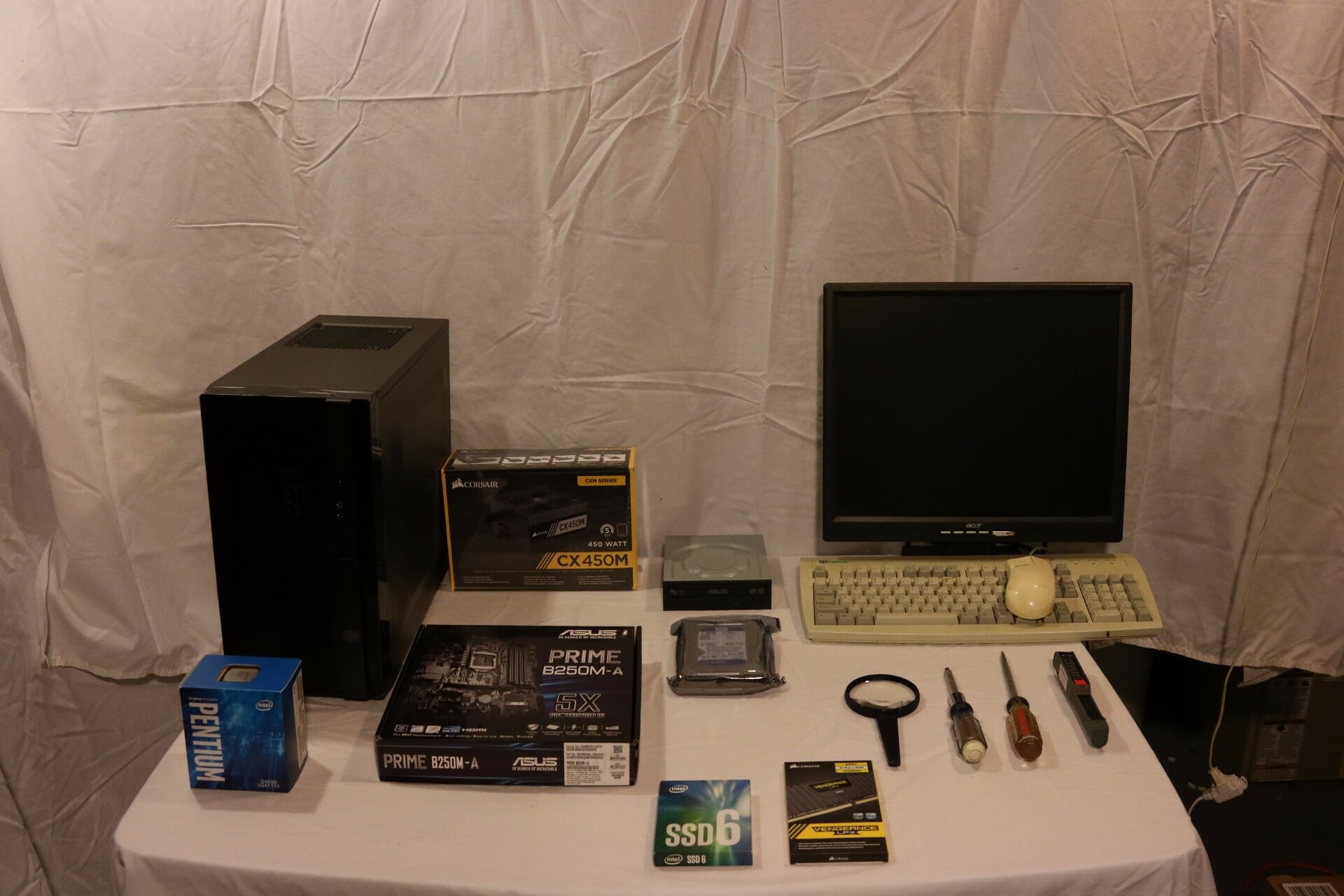
Tools Required:
- Screwdriver — A Phillips-head (cross-point) screwdriver is what is used in most PCs. Also have a straight slot available.
- Screw Extractor — If you have surgeon’s fingers you may not need this. But, if you’re human, it is likely you might drop a screw into your PC during this procedure and be too big-thumbed to get it out. A screw extractor can help you grab those screws and get them out without messing with the hardware. You definitely do not want to run your PC with loose screws in there. It could cause a short circuit.
- Flashlight — Unless you are in a fantastic lighting situation, you will likely need a flashlight to get a look of the landscape in your PC while you’re working.
- Magnifying Glass — Use with the flashlight to inspect the CPU and socket, and anything else that concerns you.
Hardware Required:
- PC Case
- Hard drive and/or solid state drive
- DVD Drive (recommended is a burner, because they are only about $20; advanced users can install an OS from a flash drive)
- Processor
- Processor Cooling Heatsink/Fan
- Motherboard
- Memory Modules (recommend dual channel, triple channel, or quad channel kits, depending on the motherboard capabilities)
- Power Supply
- Video Card (optional if motherboard/CPU has onboard video)
- Keyboard & Mouse
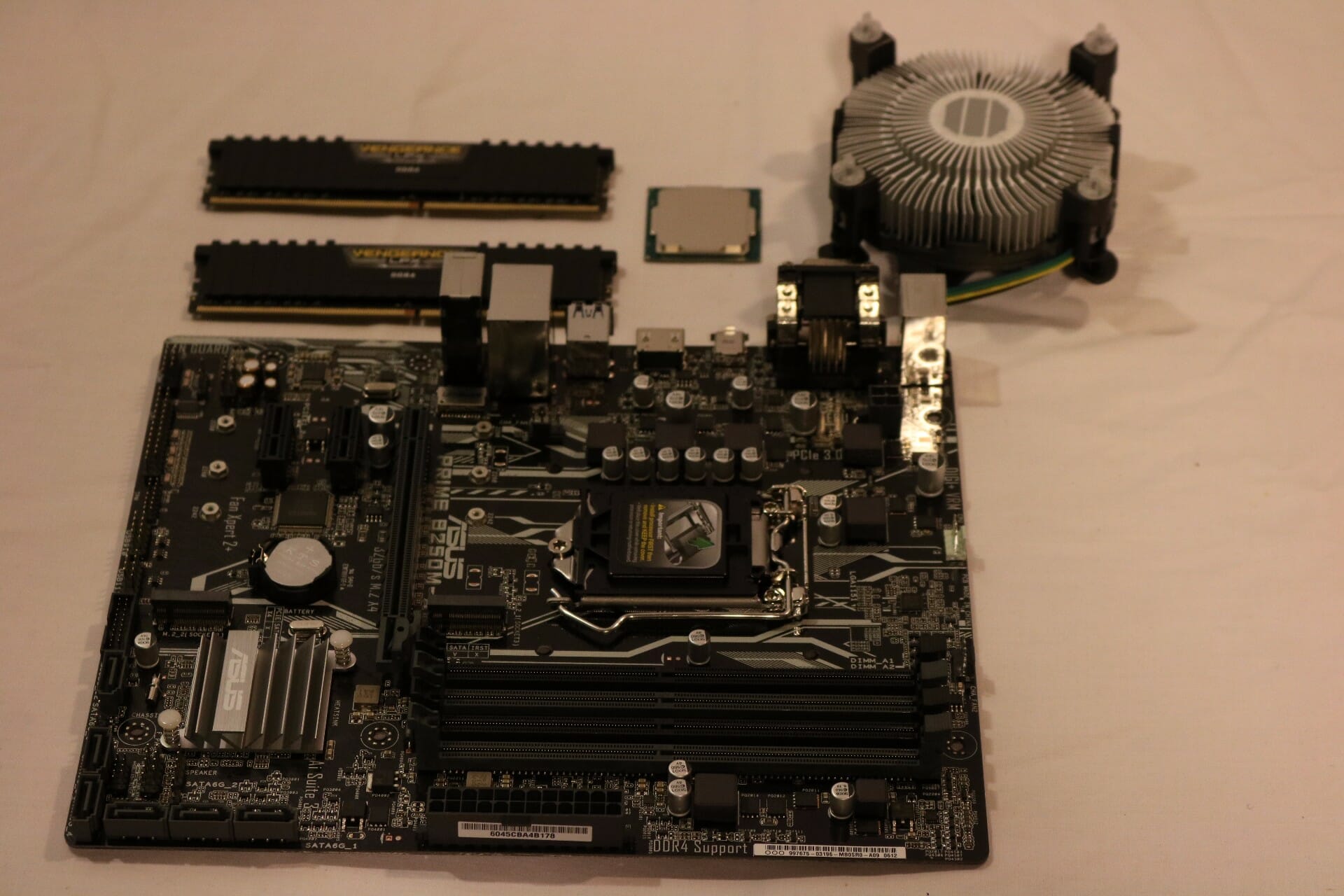
To build a basic PC, you will need at least a motherboard, a memory module, a processor with heatsink/fan, a power supply, a hard drive and a DVD drive.
Most electrically sensitive hardware comes in a static bag which is designed to protect the electronics from static electricity shock. Leave your hardware in these bags until you are ready to install them.
Software Required:
- Device Drivers (these usually come with the hardware above)
- Operating System (for the purposes of this tutorial, we will assume you are choosing Microsoft Windows as your operating system – PCMech has lots of great information on Linux and other alternatives)
Cables and Miscellaneous:
- Drive cables
- Motherboard spacers (usually come with the case, but are used to space the motherboard up off the mounting plate)
- Screws (usually a whole pile of screws will come with your PC’s case, but if you are using a case you happened to have around, you will need to collect some screws)
- Power cords (for both your PC and your monitor. They usually come with the hardware when you buy it, of course)
- CPU Cooling Compound (usually preapplied to the heatsink that comes with boxed retail processors)
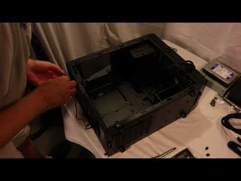
The Case
Take the cover off your new case. If you have a standard case, you take a screwdriver and remove the four or six screws located around the edge on the back of your case. Hang on to these screws and put them in a place where they will not be scattered and can be easily found later in this procedure. Once they are removed, the entire case cover comes off in one piece. With this design, the front of the case (also known as the bezel) does not move. Only the top and sides come off as a single cover.
Some cases use thumb screws rather than standard screws. It works the same way, obviously, except that you do not need to use a screwdriver to loosen and remove them. Simply twist them loose using your fingers.
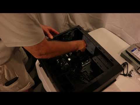
Still other cases come apart differently. Some manufacturers have developed cases using a “screwless” design. These cases are designed such that you can remove the cover simply by un-latching the parts from the chassis. With this design, you usually take hold of the bottom of the front bezel of the case and give it a nice solid yank. The front then pulls off. It is my experience that this usually requires a few tries and some muscle. These cases are usually pretty durable so you really don’t have to worry about hurting them. The sides then lift and slide off as does the top. Your case, in essence, comes apart in four pieces. Other cases come apart in a similar way, but after you take the front off, the top and sides come off together.
Each case is a little different in how it comes apart. There are almost as many designs as there are companies that make them. You may find some where you don’t even have to remove the front, and rather you just slide the sides off. With others, you can remove the whole motherboard mounting plate and card rack combo from the case by sliding it out the back. This is convenient for making quick changes to the system, although you still have to disconnect the various cables to get it out all the way. Whatever case style you have, remember to look it all over before you attempt to gain entry. You don’t want to force it and break anything – take your time.
Now that this is done, you are ready to move on.
At this point, you should have the new case in front of you with the cover removed. Before you can use it for a new system, you must prepare it for use. Go through the following checklist to make sure it is prepared. Not all of this may be necessary on your case, and if you’re using a case you already had, much or all it has likely been done already. Nonetheless, this is a useful guideline.
Now is a good time to go through the screw supply provided with the case. These are usually held in a small plastic bag nestled inside the case. Inside this bag you should find:
- Chassis screws – this is the type used to tighten down cards, etc.
- Smaller screws – just like the chassis screws, just with a smaller diameter. It is used to fasten the motherboard in.
- Standoffs – these are screws that are used to hold the motherboard about 1/8″ from the motherboard mounting plate. Their ends have a threaded opening in them that accept the smaller chassis screws. Lastly, some cases use small metal clip-looking stand-offs. They are pinched together and slipped into small rectangular holes in the motherboard mounting plate and they snap in. These are, too, a bit awkward.
Now, verify a few things have been done, if they need to be done.
- Clean Case – If the case is new, this should be no big deal. But, if the case has been used before, it could probably stand a cleaning. Clean out the inside with a rag or compressed air. Make sure the fan in the power supply is free of furry dust. Also take a rag and wipe it off.
- Install Feet if necessary – These are little tabs inserted into holes at the bottom of the case. The case sits on these tabs when on your desk. If the case has been used before or it is a more expensive case, this may not need to be done.
- Install Case Fans – Sometimes, you may want to install additional fans that screw onto a rack next to vents on the front, e.g. on the side, rear, and/or top of the case. This helps increase circulation of air through the system. Many cases already have these installed, so you may not need to worry about it. Some like to put a little filter over the hole so as to prevent dust from being drawn in. An ideal and simple setup for proper airflow is to set the front, lower fan to pull air in, and have the higher, rear fans exhaust.
- Free Up the Drive Bays – Brand new (cheaper) cases sometimes have the drive bays sealed with metal plates. It’s the most annoying thing. If you want to install any drives, and you probably do, you’ll need to remove these. Choose the drive bays you want to use (usually the ones at the top on tower cases) and remove the metal plates. These are attached by metal, so they take some cutting, prying and twisting to break them free. Be careful not to hurt the case or yourself. The plate will likely have sharp edges once removed. Better cases have these bays covered with plastic, replaceable plates which are a lot easier and make infinitely more sense.
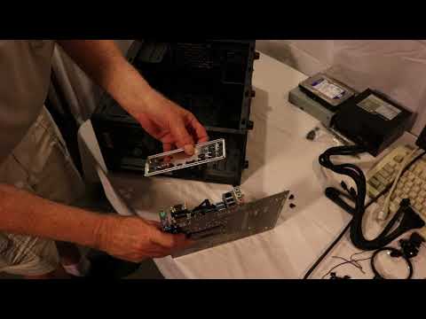
- Replace I/O Shield. The Input/Output shield is a piece of metal with various holes punched in it that allow for the motherboard connections, such as mouse and keyboard, USB and LAN to poke out the rear of your case. Since all motherboards are laid out differently, you’ll need to install the one that came with your board. Remove the old one (if installed) simply by pushing it from the rear of the case inward. It usually will pop out easily, if not use a flat-head screwdriver to pry the edges so it comes loose. Push the new one in from the inside of the case and allow it to pop into place. Check to be sure it is secure.
Some cases come with power supply unit pre-installed for you. Likewise, if the case you are using has been used before, it may have a power supply already installed. In that case, you only need to make sure it is an adequate unit for the computer you intend to build. I recommend you remove it and set it on the table for now, to assist in doing the recommended initial power-up out of the case (described later).
Processor and Motherboard Installation

The next step is to install the processor onto the motherboard. Now, at this point, the motherboard should just be sitting on your work space, preferably inside of the static protection bag in which it came. Over the next few steps, we will be installing some hardware onto the motherboard before it is installed into the case. The reason is that, in most cases, it is a LOT easier to do this with the motherboard out the case than with the motherboard in the case. This leaves room to maneuver your big hands around the components.
Installing the CPU is a pretty straight-forward process. The real risk is to the CPU. Doing this step too fast or carelessly can result in damage to the processor. Therefore, don’t get nervous. It is an easy step, but do it with care.
There are 2 common interfaces for CPU’s today: Intel Socket LGA 11xx/20xx and AMD AMx/FMx. But, they all boil down to two basic types: The Zero Insertion Force (ZIF) socket and the slot. Most processors in use today use a socket to connect to the motherboard, and the type of socket in use is typically the ZIF socket. The ZIF socket opens and closes using a small lever. When the lever is down, the CPU is locked into place. When in the upright position, the processor is loose and can either be installed or removed.
All modern systems make use of the zero-insertion force (ZIF) socket. Therefore, this procedure is relevant with that setup. To install a processor using this type of interface, follow this procedure (Intel processor instructions below, for AMD processors please move on to the next page):
Intel
The pins are in the socket and the CPU has pads for the pins to contact.
Open ZIF Socket
This is done by grabbing the lever on one side of the socket and opening it. Pull the lever from the closed, level position, to the open, vertical position. You may need to pull the lever out a bit before it will open. Do this slowly and don’t force it. You don’t want to break the socket. On the way up, you may experience a little more force. This is normal. Open the load plate and remove the plastic cover. Inspect the socket carefully with a magnifying glass for any damaged pins.
Orient The Chip
There are notches in the processor and matching tabs in the socket so it will only go in one way.
Insert Processor
Bearing in mind the orientation, lay the chip on the socket. Make sure the processor is laying flat on the socket pins. Close the load plate.
Close ZIF Socket
Apply very light pressure on the load plate, and close the lever. When down, make sure the lever snaps into place.
Installing the Heatsink / Fan (Intel)
Retail Intel fans have 4 posts that go into 4 holes in the motherboard around the socket. They can be installed 4 ways, so orient it so the fan cable will reach the CPU_FAN motherboard header. With a straight slot screwdriver in the slot on top of each post, twist each one clockwise (against the direction of the arrow) to make sure they are in the locked position. Twisting counter-clockwise will unlock the posts for later removal or to try again if you have problems getting them locked down. There is 90 degrees of motion. Remove any protective cover from the bottom of the heatsink and verify there is heatsink compound on the part that will contact the top of the CPU.
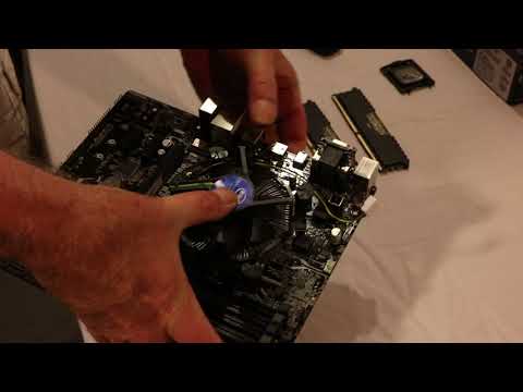
Next, lower the assembly onto the CPU, ensuring the 4 posts all start down into the holes on the motherboard. Now, this is where it can get a bit tricky and it does help to have an extra set of hands if available. Pick up the motherboard, and support it on one hand with your fingers “tented” around the socket area. If you have another set of hands, steady the assembly by pushing down on the top of it lightly. Take your thumb and apply steady pressure down on each pin till you hear it “snap”into the motherboard, using a criss-cross pattern – push one down, then the one on the other side, then repeat with the other 2. What you are trying to do is avoid flexing the board.
Finally, visually inspect the back of the board to make sure the pins are fully snapped down. If not, unlock the pin, lift the pin out of the hole, relock the pin, and try again. Connect the fan lead to the CPU_FAN header on the motherboard.
AMD
The socket has pinholes and the pins are on the CPU.
Open ZIF socket
This is done by grabbing the lever on one side of the socket and opening it. Pull the lever from the closed, level position, to the open, vertical position. You may need to pull the lever out a bit before it will open. Do this slowly and don’t force it. You don’t want to break the socket. On the way up, you may experience a little more force. This is normal.
Orient The Chip
There will be a gold triangle on one corner of the CPU on the circuit board outside the metal spreader cap. This aligns with a small molded triangle on one corner of the socket, some motherboards may also have a triangle on the circuit board outside the socket. Remove any protective plastic from the processor and inspect the pins with a magnifying glass for damage. Be VERY careful not to bend any pins, they are very delicate.
Insert Processor
Bearing in mind the orientation, lay the chip on the socket and ensure the pins drop into the holes. It should just drop in without applying any pressure. Make sure the processor is laying flat in the socket and all the way in.
Close ZIF Socket
Apply very light pressure on top of the processor, and close the lever. When down, make sure the lever snaps into place.
Installing the Heatsink / Fan (AMD)
The retail AMD heatsink installs with clips over tabs on the side of the socket. It can be installed one of 2 ways, determine which way works best for you by checking clearances and so the fan cable will reach the CPU_FAN motherboard header. Remove any protective cover from the bottom of the heatsink and verify there is heatsink compound on the part of the heatsink that will contact the top of the CPU. Set the heatsink on top of the CPU and hook the clip without the cam lock over the tab on the side of the socket. Ensure the cam is unlocked (rounded side facing up) and hook that clip over the tab. Rotate the cam 180 degrees to lock the heatsink down. Connect the fan lead to the CPU_FAN header on the motherboard.
Today’s processors are running quite hot. Advancements are being made to make them run cooler at higher speeds, but the importance of a high quality heat sink and fan cannot be overstated. PCs that are not properly cooled can be quite unstable, or at its worse, it may not even boot properly.
It used to be that you could attach a heat sink and fan to your processor directly and not worry about it. Today, though, processors run too hot to do this and expect a reliable PC. One must use heat sink compound to seal the gap between the heat sink and the top of the processor.
If you are installing an aftermarket cooling device, follow the instructions that come with the device and make sure that heatsink compound is correctly applied.
Installing Memory

You should now install your memory modules. For the purposes of this step, we are assuming that you have already chosen the appropriate memory for your PC. So, we will jump right into installing the memory.
It is important that you consult the manual for your motherboard to see about any particular sequences in which memory should be installed on your board. Some boards require particular sequences of memory installation, usually depending on the memory capacity, type, etc. Other boards have no required sequence at all, and you can choose any slot you wish to install your memory. Most new motherboards support Dual Channel RAM, some support triple and even quad channel. This is a technology that allows a performance increase when using 2, 3, or 4 matched sticks of RAM. Consult your motherboard manual on which slots to use for multi-channel.
The installation of modules is basically the same regardless of type, even though each module type looks a little different.
Ground yourself by touching an unpainted metal object. This will discharge any built up static electricity in your body.
Pick up the memory module by its edges.
Decide which slots you are going to use and orient the memory module over it. The module slot will have a small plastic bridge which will be off-center in the socket. This matches up with a notch in the pin array of the memory module itself and ensures that you insert the module in the proper alignment. Open the locks by pushing them outward. Some boards only have a lock at one end, the other end being fixed.
Insert the memory module
With DIMMs they go straight in. Make sure the notches in the RAM line up with the little bumps in the slot.
Lock the module in place
With DIMMs, all you have to do is continue to press the memory module down until the ejector clip or clips on either side of the memory slot automatically get pushed into the closed position. Sometimes, you may need to help the ejector clips close, but the idea here is that those clips need to close so as to lock the module into place. If they do not close, it is because the module is not inserted all the way into the slot.
Repeat this procedure for any other memory modules you are going to install.
Power On Self Test (POST) Check
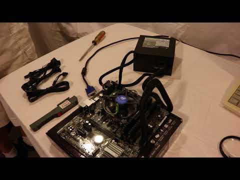
At this point, your have your processor, heat sink and fan and your memory installed onto your motherboard. In most cases you are now ready to install your motherboard into the case. However, I recommend you do a quick “out of the case” power-up to make sure your core components work.
Set the motherboard on a non-conductive surface. Do NOT use the anti-static bag that the board came in. I use the box that the motherboard came in, covered with a piece of paper in case the box is printed with metallic ink. If your board/CPU did not come with onboard video, insert your video card into the proper slot fully. Most new boards will use the primary PCI-Ex16 slot, which is closest to the CPU. Most also have locks to keep the card in the slot. Some are tabs on the back side of the socket, others are locks at the back of the socket similar to the memory slot locks. If it’s one of those, make sure it’s unlocked.
Next, set the power supply on the table next to the board. Insert the main ATX 24 pin connector (some power supplies will have a 20 pin plug with a separate 4 pin plug that clips onto the side of it). Insert the 4 or 8 pin (some power supplies will have 2 4 pin connectors that clip together) CPU connector into the socket, some boards have a 4 pin, others have an 8 pin. These connectors are all keyed so they will only install one way, the correct way. If the video card has auxiliary power connectors (labeled PCI-E) connect the appropriate power supply cables. There are 6 and 8 pin PCI-E connectors, some cards have both, some power supplies have both. Other power supplies will have “6+2” which can be used either way, like the 20+4 ATX and 4+4 CPU connectors. Connect a monitor with a VGA or DVI cable to the video port on the board or video card and turn it on.
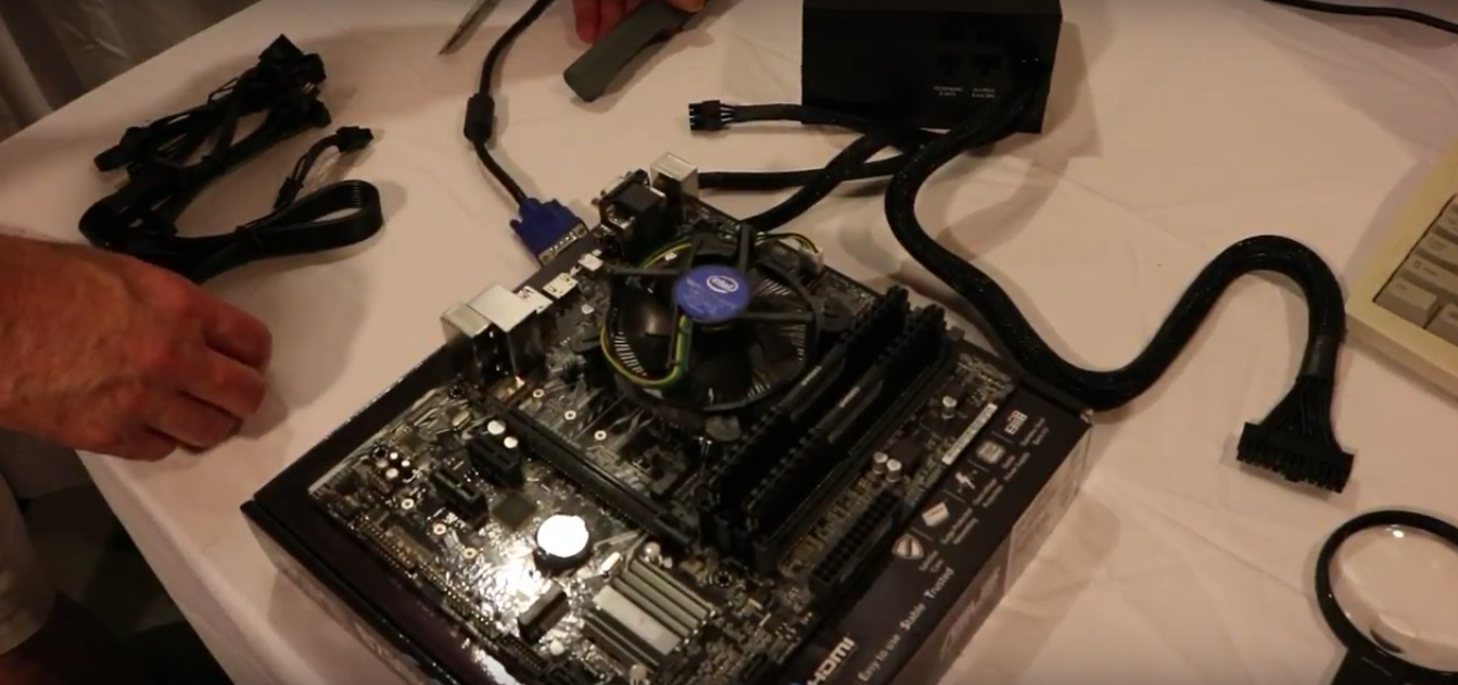
Plug the power supply into AC power, and turn on the rocker switch (if equipped). Using the motherboard manual, locate the 2 pins for the power button – usually labeled PWR_BTN or similar. With a small screwdriver, momentarily short the 2 pins together. It only takes a momentary touch – do not hold the screwdriver on them for more than a second. Some motherboards have a power button on the board that can be pushed to accomplish this. The CPU fan should start running, watch the screen. If you see any kind of display – the motherboard splash screen or POST data, or even a blinking cursor, you are good. Turn it off with the rocker switch or by pulling the AC power cord and disconnect the power supply from the board. If you installed a video card, remove it, to unlock the tab type just carefully bend the tab away from the card till the locking tab clears, eject the other type like you would with ram.
Installing the Motherboard into the Case
Now you need to install the motherboard into the case. If you’re following this tutorial, the CPU, fan and memory will already be installed onto the motherboard, so you will be installing this whole setup into the case now.
Turn your PC case onto its side. If you are using a case in which the motherboard mounting plate can be removed, you may wish to remove it now and install the motherboard outside of the case itself.
Locate the holes on the motherboard and the holes on the case or motherboard mounting plate. You might want to hold the board just above the case motherboard plate and see which holes on the case line up with holes on the motherboard. All motherboards have mounting holes in different places.
Now gather your standoffs. Screw them into the holes in the case or mounting plate that line up with holes on the motherboard. Some cases have pre-installed standoffs or even raised pads that don’t require standoffs; you need to determine first if this is the case. You can tighten them with a 3/16″ nut driver or by hand. Some cases have small spacers that snap into place. With these, you push them through the mounting plate from the back side and they will snap into place. Remove any pre-installed standoffs that don’t have a matching motherboard hole.
Take the motherboard by its edges and hold it over the case. Align it so that it is properly aligned with the rear connectors facing backward, etc.

Lower the motherboard into the case. Sit it on top of the standoffs you just installed so that each standoff lines up with a screwhole on the motherboard. You will have to lower it just a bit closer to the front of the case than perfectly aligned, then slide it back carefully so the ports go through the I/O shield. This can be tricky, watch carefully so the ports go through the holes without catching on any of the spring tabs.
Insert the screws you will use to tighten the board down and screw them down very lightly. Then snug them up using a criss-cross pattern of some sort. They don’t have to be real tight, just snug. If you were installing the board to a removable mounting plate, install the motherboard mounting plate back into the case. On some cases, the plate is installed from the side. On these, you insert the bottom edge of the plate into a guide rail on the bottom of the case and then rotate upward. The top edge of the plate will contact the case, at which point you can screw it in or a spring loaded handle will lock it in. On other cases, the plate may slide in a different way, from the rear for example. These plates are then easily removed later if you ever need to remove the motherboard.
Double check your work. Check to be sure that the back of the motherboard is not touching any part of the case or mounting plate. Make sure the slots and connectors line up with the holes on the back of the case. And definitely be sure that the board is rigid and tight. If you press down on the board at any point, it should not bend down.
Connecting the Motherboard
Now it is time to begin connecting your newly installed motherboard to the various wires of your case as well as its power source.
NOTE: If you have been working on a removed motherboard mounting plate, you will need to install the plate back into the case in order to be able to make the connections below.
Installing the power supply
Take the power supply unit and line it up for placement into the PC case. The wires should face forward. Fan location varies depending on whether it’s a top or bottom mount. Top mount fans should face down. Bottom mount can go either way, some cases allow mounting both ways, others do not. If you have a choice, if there are openings in the bottom of the case under the power supply, I prefer fan down.
Insert the PSU into the case. Sometimes this takes a little maneuvering to get it into position.
Once the unit is in place, check the back of the case and make sure the holes on the rear of the PSU line up with the screw holes on the case. If they do not, you may need to turn the power supply over.
Using your screwdriver, tighten the PSU down using standard chassis screws.
Make sure the voltage is set correctly. There is a little switch on the back that lets you switch between 120 or 220 volts. In the United States, it’s 120. If you are in a country overseas, it’s most likely 220. If you use 220, make sure the cord is rated for it. It should say on the side of the cord. It’s easiest to just check this now while you’re thinking about it.

Connect the power to the motherboard.
Insert the main ATX 24 pin connector (some power supplies will have a 20 pin plug with a separate 4 pin plug that clips onto the side of it). Insert the 4 or 8 pin (some power supplies will have 2 4 pin connectors that clip together) CPU connector into the socket, some boards have a 4 pin, others have an 8 pin. These connectors are all keyed so they will only install one way, the correct way.
Connect the CPU fan to the CPU_FAN header on the motherboard.
Study the case connectors on the motherboard and match them up with case connector wires. The connectors are usually a big block of pins located in the lower section of the board. Some boards have a small block that you connect the wires to, then the block plugs into the board header. Asus calls this “Q-Connect”. Some boards label the pins, but it is best to have your manual since it can sometimes be difficult to determine which label goes to which set of pins. If you have a good case, each connector will be labeled to tell you what case feature it leads to. If this isn’t the case, you may have to physically trace the wires back to see what feature it goes to. When connecting, consult the manual for pin 1’s, to make sure each connector is plugged in the right way. Remember, if the particular case feature is not working later, you may only have to turn the connector around on the motherboard. The next steps will walk you through connecting each wire.
- Connect the power switch – The connector is usually labeled PWR_SW, or maybe just PWR, but you must make this connection. It can be plugged in any way, just make sure you connect it to the right pins. Doing this wrong could cause your system not to start later.
- Connect the reset switch. It can be plugged in any way, just make sure you connect it to the right pins. The pins may be labeled RST or RESET, but it is best to also consult the manual.
- Connect Power LED. Can be labeled PLED. Polarity sensitive, if you get it backwards, the LED won’t work. You won’t hurt anything, just flip it over.
- Connect the hard drive activity LED. It is usually labeled HDD, HDD_LED, or similar. It is also polarity sensitive. If you get it backwards, the light may either never come on later or will stay on all the time when the PC is running.
- Connect the PC speaker (if equipped). Most cases put this onto a 4-wire plug. Just plug it in to the 4 pins on the motherboard. Other cases put the speaker connector on two 1-wire plugs. In this case, plug them into pins 1 and 4. I never could figure out why they did that. Some cases come with a little piezo speaker in the accessory bag. Some motherboards have a built-in piezo speaker and don’t have speaker pins.
- Connect the other front panel leads (audio, USB, 1394, eSATA, etc. to the appropriate headers.
Double-check your work, as always. Note that if an LED does not light up, its case connector needs to be flipped 180 degrees.
Installing Drives

DVD drive
Choose which 5.25″ external drive bay you want to install the DVD drive to and remove the face plate off of that bay. Save the face plate for future use. Now, slide the drive into the bay from the front. Make sure the front of the drive is flush with the front of the PC. Also make sure the screw holes on the drive align with the screw holes on the drive mounting rack.
If your particular case has a removable rack then you may need to remove the rack from the system to secure the drive. But, in using removable racks, you need to pay attention to which set of screw holes to use on the rack which will result in the drive face being flush with the front of the PC. In some cases, it is still easier to install the drive from the front and make it flush just to see which screwholes to use. Then you can remove the drive rack, making note of which holes to use. Some cases have toolless racks where you slide the drive in from the front and close locking tabs or levers.
Hard drive/SSD
Before simply following the directions below on mounting the hard drive, pay attention to where you put it. Technically, you can put the hard drive in any free bay of your case, but there are a few considerations:
Hard drives generate heat, especially the drives with the higher rotation speeds. Therefore, it is best to place these drives as far from other hardware as possible. Give them room to breathe.
If it is necessary to install a drive cooler, make sure you have room for it.
Some cases give room under the power supply to install a hard drive. This is bad idea! A power supply is like a magnet, and magnets and your data do not go together. Don’t install a hard drive anywhere near the power supply. Keep your hard drive near the front of the case.
Okay, let’s install the actual drive:

Determine which drive bay to install the hard drive into. In most cases, the hard drive usually goes into a 3.5″ slot toward the front of the case, near the bottom. These bays do not have a corresponding opening to the front of the case simply because there is no reason to see the hard drive from the front. Some cases use a removable drive rack to hold the hard drive. If your case uses this type of setup, remove the rack now.
Slide in the hard drive. If you are using a removable drive rack, just push the drive into the rack so that the screw holes line up. If your case has the drive rack as part of the chassis, then just lift the drive into the case and line up the screw holes on the drive with the drive rack. If the rack faces fore and aft, be sure the drive connectors face toward the back of the case. If it’s a sideways rack, determine which side it is designed for, ensuring clearance for the power and data cables.
Fasten the hard drive into place using your screws. This is easy to do on removable racks. In non-removable racks, tightening down screws on the far side of the hard drive can be a problem, because the screws are not highly visible and thus it is hard to get to them with a screwdriver. It can take a little creativity to get at them. Most cases which have this problem have little holes where you can stick the screwdriver through and tighten the screw beneath. If the screw is not in there, I’ve even had to do a controlled drop of the screw onto the hole and then use the screwdriver to position it into the hole. It can be a real feat to do it sometimes, and this is one reason some manufacturers went to the removable racks. If you have a magnetic screwdriver that can hold the screw, this might be less of a problem for you. Some hard drive racks are toolless, or require screws and rubber bushings be installed on the drive before inserting it into the rack.
For SSD’s, some cases have 2.5″ bays for them, if not, you will need a 2.5″ to 3.5″ adapter which may or may not come with the drive or case.
If using a removable drive rack, you can now install the rack back into your case. Some racks are fastened into place using a simple thumb lever. Others need to be screwed in. If you have any other drives which you are installing as you build your PC, then repeat the steps above for the other drives.

Attach the power cable. Choose an unused power lead from the power supply and plug it into the power plug on the drive. The plug will be keyed so that it will only go in the correct way. SATA power connectors are thin and black.
Attach the data cables to the drives. Start with the lowest number port (usually 0 or 1) for the SSD/hard drives, then the DVD drive should be last. Use the ports native to the motherboard (i.e. Intel or AMD) first, avoid 3rd party controllers (i.e. Marvell, Jmicron, etc.).
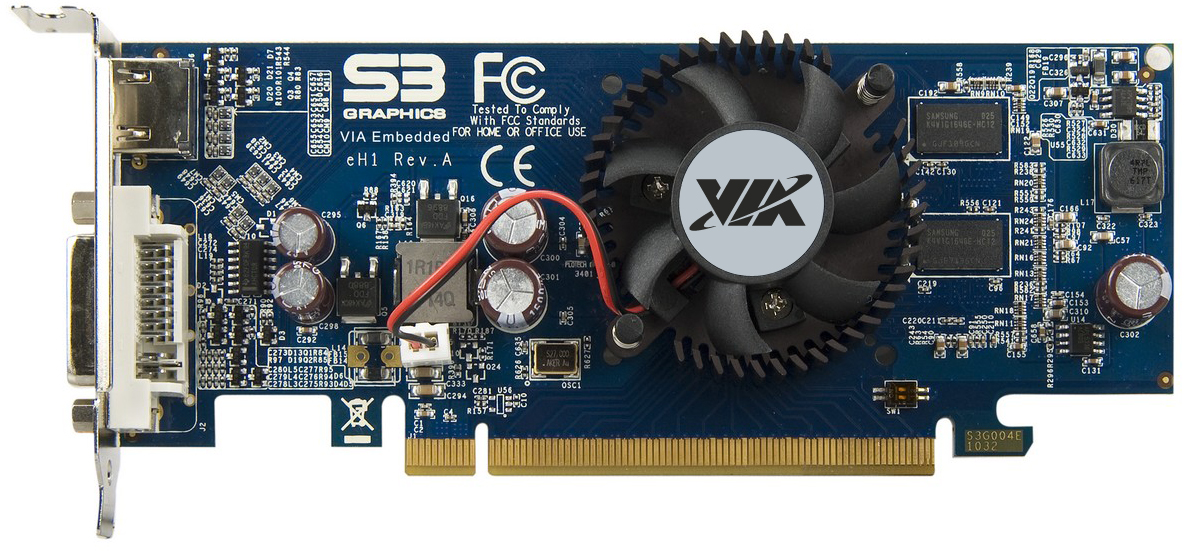
Video Card Installation
You must have a video card installed or operable onboard video in order to complete this tutorial so that you can see the output from your new PC once you turn it on. Installing a video card (or any expansion card for that matter) is incredibly straight-forward and easy.
Find the correct slot for your video card. Most new boards will use the primary PCI-Ex16 slot, which is closest to the CPU. Most also have locks to keep the card in the slot. Some are tabs on the back side of the socket, others are locks at the back of the socket similar to the memory slot locks. If it’s one of those, make sure it’s unlocked.
Remove the case insert that corresponds to the slot on the motherboard. This is usually done by unscrewing, but some cases have punch out inserts. If unclear, what we are referring to by “insert” is the small plate which covers up the rear slots on your case which your expansion cards will emerge from.
Insert the video card in the slot. You might need to rock the card in, inserting one end first, then rocking the rest of the pins into place. When pushing down, make sure the motherboard does not flex. If the board tends to bend, it may be necessary to place one hand underneath the board to hold it up. Also, in some cases, you may have a problem with the leading edge of the video card’s metal plate hitting the case behind the motherboard. The result is that it keeps you from being able to push the card in all the way. I’ve tried all sorts of weird methods to fix this problem, including taking pliers to the card and actually bending it. Sometimes, you can grab a flat-head screwdriver and pry the hole wider that the card’s lip protrudes into. But, in most cases, just playing with it for a bit will do the trick.
With the video card inserted into the correct slot, it will probably sit there with no support at all. It is still, though, necessary to tighten it in using a screw. The card’s metal plate will have a notch for a screw and it will line up with a screwhole on the side of the expansion hole on the rear of the case. Just insert a screw into that hole and tighten it.
Double-check your work. Make sure the card is securely in place and, if your video card has a cooling fan on it, make sure no ribbon cables or power leads are getting into the fan blades. If the video card has auxiliary power connectors (labeled PCI-E) connect the appropriate power supply cables. There are 6 and 8 pin PCI-E connectors, some cards have both, some power supplies have both. Other power supplies will have “6+2” which can be used either way, like the 20+4 ATX and 4+4 CPU connectors.
Checking Your Work
Well, you have gotten this far. Congratulations! You have now completed the hardware portion of putting together your PC.
Admittedly, if you are following this tutorial to the letter, your PC is rather bare-boned at this point. You may be installing some additional hardware such as a wireless network interface card (modern motherboards have onboard wired Ethernet adapters), a premium sound card (modern motherboards have onboard sound), maybe a dial-up modem or other hardware. Some people like to install everything right away. Usually when I build a PC, I like to start with the basics. The reason is that it makes the installation process of your operating system easier. Once you have your operating system installed, you can then go in and install your additional hardware and get those items working one at a time. It can be a little daunting to try to get everything working at the same time, especially simultaneously to installing the operating system itself.
Now, you are about ready to turn your new PC on for the first time. But before we do so we need to give everything the once over and make sure we didn’t miss something. So, with a flashlight, check all of your work. It is better to “waste” the time than to engage in wasted time trying to track down why the system will not boot.
- Review all your connections and installations as completed in prior steps. Here is a list of highlights to guide you:
- Drives properly connected to the power supply.
- CPU fan attached to the CPU fan power connector on the motherboard.
- The 110/220 volt switch on the back of the power supply is configured properly for your area.
SATA data cables attached correctly and securely - All connections tight, no connectors off by one set of pins
- No wires or cables protruding into fan blades
Power switch connector on ATX machines properly connected to the PWR_SW pins on the motherboard. If this is not properly done, the machine may not even turn on when the switch is pressed.
It is time for the moment of truth. To see if this thing works!!
Let’s get everything connected and prepared to turn it on:
Connect your mouse and keyboard
Connect your monitor to the video card and connect the power cord to the monitor.
Connect the power cord to your power supply on the PC itself.
Power On!
Okay, now for boot up time!
Turn your monitor on.
Before hitting the power switch, take note of what to expect. If you notice something awry right away, you may need to quickly turn the PC back off. Here’s what to look for:
- The power LED should turn on
- The CPU and PSU fans should start spinning
- The hard drive should power up
- You will see the BIOS screen first (or the motherboard manufacturer’s splash screen)
- You may hear one beep from the PC speaker. It is possible you will get more than one beep, which indicates an error which we will address.
- You may also get a “CMOS checksum error” or another error saying the CMOS or time isn’t set.
- Know what key(s) to hit to enter CMOS setup. This will be shown on the bottom of the screen usually during the memory count. You will want to press the stated key combination to enter setup immediately because CMOS setup is the next step.
If you hear any weird sounds such as grinding, scraping, or loud whining, be ready to turn the system off immediately.
Keep in mind that if you miss the stated sequence to enter the CMOS setup before the boot sequence moves on, there is nothing wrong with just hitting the reset button and rebooting until you do catch what it is. It will not hurt your PC to reset it immediately or turn it off quickly if you notice a problem.

Press the power switch. If it powers up, observe the system closely. As soon as the BIOS or splash screen appears, press the appropriate key(s) and enter CMOS setup. The correct key combination should be visible at the bottom of the screen. Sometimes it pops by too quickly for you to see which keys to press. No problem. Don’t hesitate to just hit reset and try again, as stated above.
If everything started up as expected and you successfully got into the CMOS setup screen, just let it sit there while you take out a flash light and inspect the system as it is running. Make sure all the fans are running. Make sure all the fans are operating smoothly and not generating any strange noises. Make sure the case power LED is on. If the HDD light is stuck on, shut down and reverse the connection. If any of the fans are not spinning, turn the PC back off immediately and plug the fan in. You do not want to run the PC for long without fans running, especially not without the CPU fan.
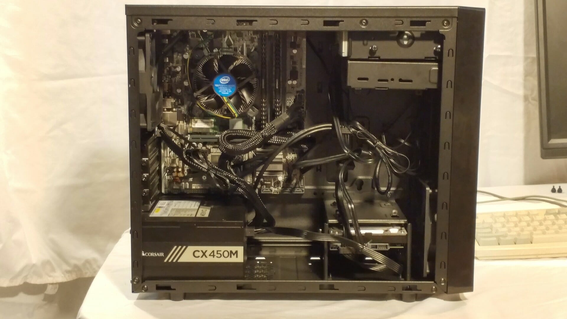
Shut it down and now is the time to bundle and dress all the cables neatly, you can use either zip ties or twist ties to help with this. The neater it is, the cooler it will run. Modular power supplies help a lot with this, as you only connect the cables you need to the power supply. Some cases have provisions for running cables behind the motherboard.
The PCMech Community Forums
If, at this point, you are incredibly frustrated because your new computer is not working and you just cannot seem to find the problem, do not despair. You’re not alone! We have an extensive forum community at PCMech. In the forums, you can ask questions and get answers from many incredibly knowledgeable people. All you need to do is register. It is absolutely free. The forums are a great asset for PC Mechanic users, allowing everyone to learn from others’ experiences. Go to the forums!
Fire it up and go into the CMOS setup.
Your next step is to make sure your BIOS is using the proper settings. While some users like to use the BIOS to tweak the system into running like greased soap, during an initial build it is best to keep settings conservative, which usually means leaving them at their defaults. Remember at this point we are most interested in getting this PC to work. I will discuss the necessary steps. The optional steps are beyond the scope of this basic tutorial and can be researched separately. Have the motherboard manual in front of you opened to the section that describes the CMOS settings.
New motherboards have what’s called a UEFI bios. It’s a graphical bios with basic and advanced modes. I’m going to talk in generalities because different boards are set up differently. The steps below are sort of a checklist.
- Set the correct date and time.
- Verify it recognizes your CPU for what it is and the correct amount of ram.
- Check the ram speed and voltage, if the auto detect doesn’t have it right, change it. With modern Intel based systems, anything faster than 1333MHz ram has to use XMP (Intel Extreme Memory Profile). Find out in the manual how to set this.
- Verify that all drives are properly seen, and make sure the SATA controller is set to AHCI. For faster boot, disable the unused 3rd party controllers if equipped.
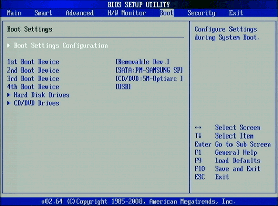
- Set the boot order. I recommend you set it to DVD first, then your hard drive or SSD that you will be installing the OS on. There is usually a separate screen for setting hard drive/SSD order if you have multiple drives. Disable network boot.
- Check to make sure the integrated peripherals you are using are enabled, and the ones you are not are disabled.
- Save and exit, it should reboot to some kind of error screen, saying no bootable device or missing operating system or something like that.
Assuming you handled that properly, the PC should be up and running. Now that the PC is just sitting there running, it is a good time to test a few things before proceeding further. Hit the reset button and enter the CMOS setup again.
Check the following:
- Check the LED’s on the front of the case. During boot-up, the HDD LED should light and then go off. If it does, it is connected properly to the motherboard. If not, try reversing the leads on the LED plug, or just turning it around. You can also check that the power LED lights.
- Check the hard drive. Make sure it is spinning. You can hear/feel it. However, you can’t tell with a SSD because it’s not a mechanical device.
- Check the fans. Make sure the CPU fan, power supply fan, and case fans are all spinning without any wires in the way. If your video card happens to have a fan, make sure it spins freely as well.
- Make sure the DVD has power by hitting the eject button and seeing if it opens.
Let the system run for 10-15 minutes. While it is running, go into your CMOS setup and go to the PC Health screen so that you can monitor the CPU temperatures while it is running. The purpose in doing this is to ensure that the processor is being adequately cooled and will not lead to instability. If you choose, you can also – CAREFULLY – ground yourself and then reach in and gently touch the sides of the CPU and heat sink as it is running. If the heat sink is lukewarm to the touch (not too hot to touch) then it is doing its job properly. During this testing period, you can just let the PC run for a bit. If, after several minutes, the heat sink gets too hot or the temperature readouts become abnormally high, or if the PC Health screen freezes and you cannot do anything with the keyboard, then you likely have a cooling issue with your processor. You are either running a cooling fan which is not adequate for your processor or there is an issue with inadequate heat transfer between the processor and the heat sink, which means you might need to re-install the processor and do a better job of using heat sink compound this time. With Intel processors, this can happen if any of the pins are not completely snapped into the motherboard.
Completing Setup
Now that we’ve completed the hardware setup successfully, you’re now ready to get the PC set up as you want it.
- Make sure Windows Firewall is on. You can make sure you’re connected to the Internet afterwards as well, whether through an Ethernet cable or by configuring your wireless card.
- Next, go into Control Panel and open Windows Update. Scan for updates, and take all important updates and any optionals you want. I don’t recommend you take any hardware driver updates unless there are no manufacturer’s drivers available. If you want to update drivers, go to the manufacturer’s site and get the latest from there. After the updates are installed you will probably have to reboot. Repeat until there are no more updates available that you want.
- Now, install some kind of security software. Windows Defender in Windows 7 is not adequate, but it is in Windows 8/8.1./10 There are several free alternatives that work well.
- Now, if you’re running Windows 7, you’ll need to activate Windows. To activate, you simply follow the wizard. It is easiest to activate via the internet. Doing it this way is very automatic and is done using a secure server. If your PC is not internet connected, you can activate it via telephone. Call the toll-free number on the screen, read off to the operator the number displayed on the screen and type in the confirmation number they give you.
At this point, your new PC is now ready to go! Next, you can begin installing your software and customizing your new computer to suit your needs.
Congratulations. Enjoy your new PC!


18 thoughts on “How to Build Your Own PC”
card with ddr3 ram ??
But great article and look forward to the one click download vice page by page!
I would be interested in a small form factor build, with SSD as the primary drive. It seems easier to buy ready-made than to build from parts though. Any ideas?
Larry
To be honest, an article should neve go more than 2 or 3 web pages tops! Its easier to scroll down a ways to read an article than to click through multiple pages (or slide shows). Especially if the reader is pressed for time and decides to copy and paste the entire article in a text file to read later.
I put together a monthly newsletter for an organization (being a meber). I use LibreOffice Writer to create the newsletter (which can be published on the organization’s web site) and Writer’s PDF option to create a file to send to other members.